About Carrier Board
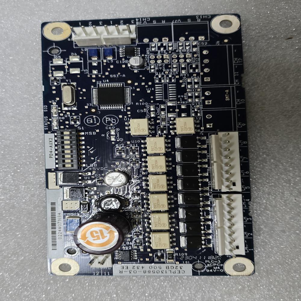
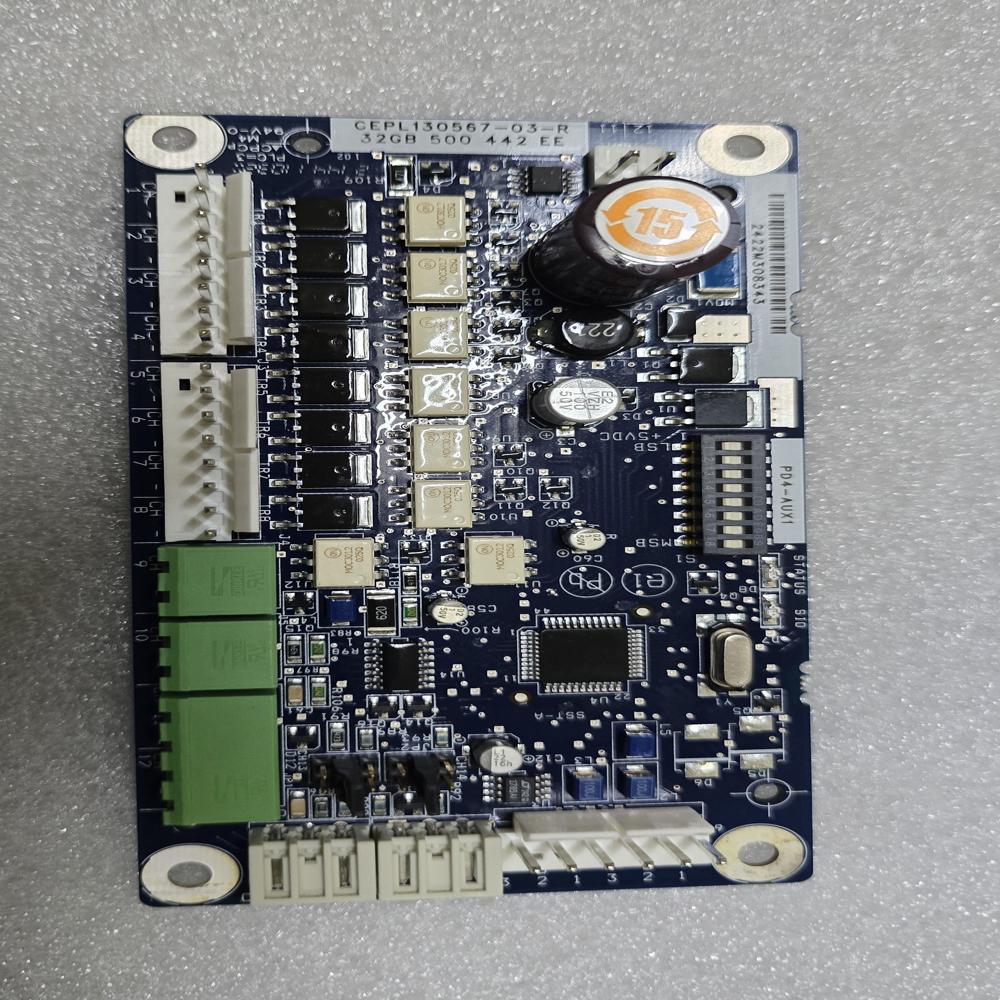
Carrier Fan Auxiliary (Aux) Control Board primarily used in industrial HVAC systems and chillers to manage fan speed, safety interlocks, and system diagnostics. It is a critical component for maintaining system stability and optimizing the performance of blower motors in units like the 30RB/RQ series chillers
- Key Functions: Manages Multi-Tap ECM motor control for variable speed efficiency, provides flash code diagnostics, and performs dissipation system self-tests.
- Safety: Includes intelligent load control algorithms to prevent overloads and minimize wear on the blower motor.
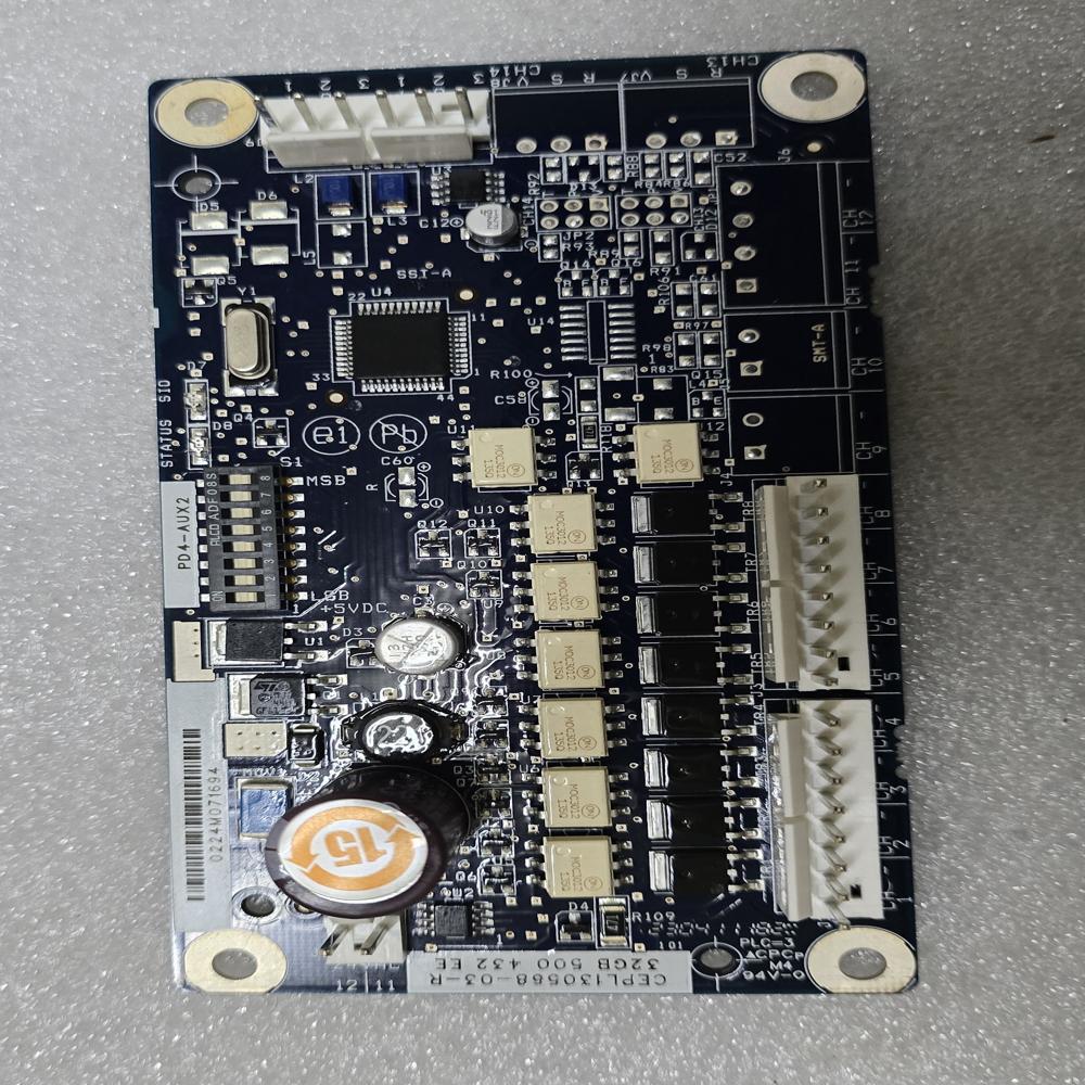
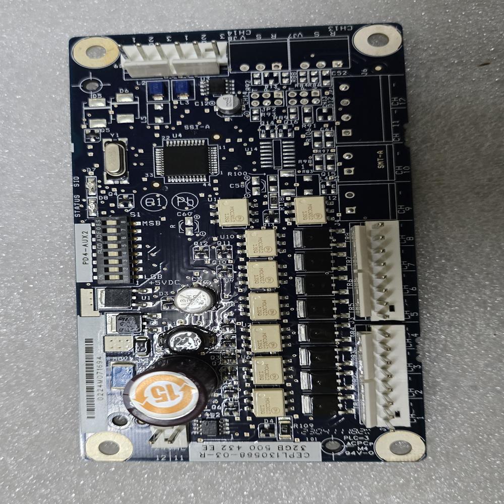
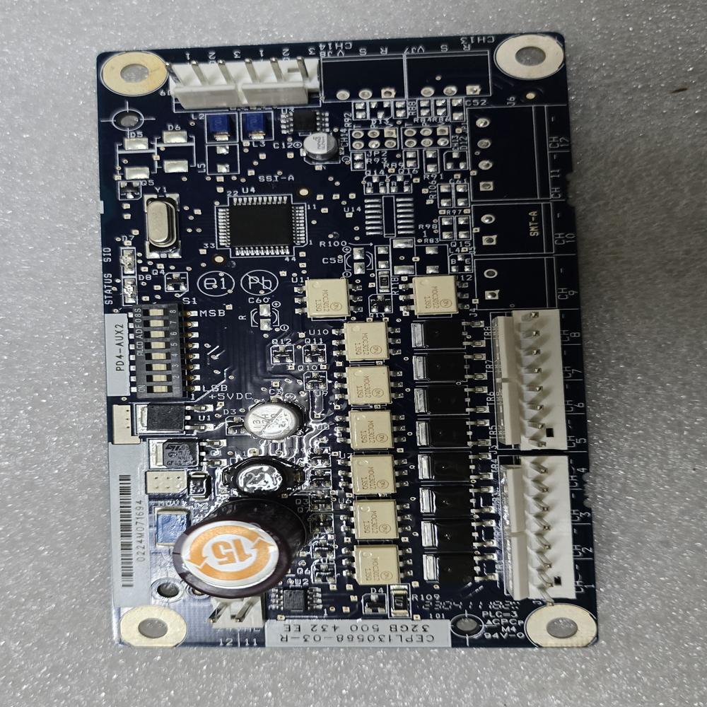
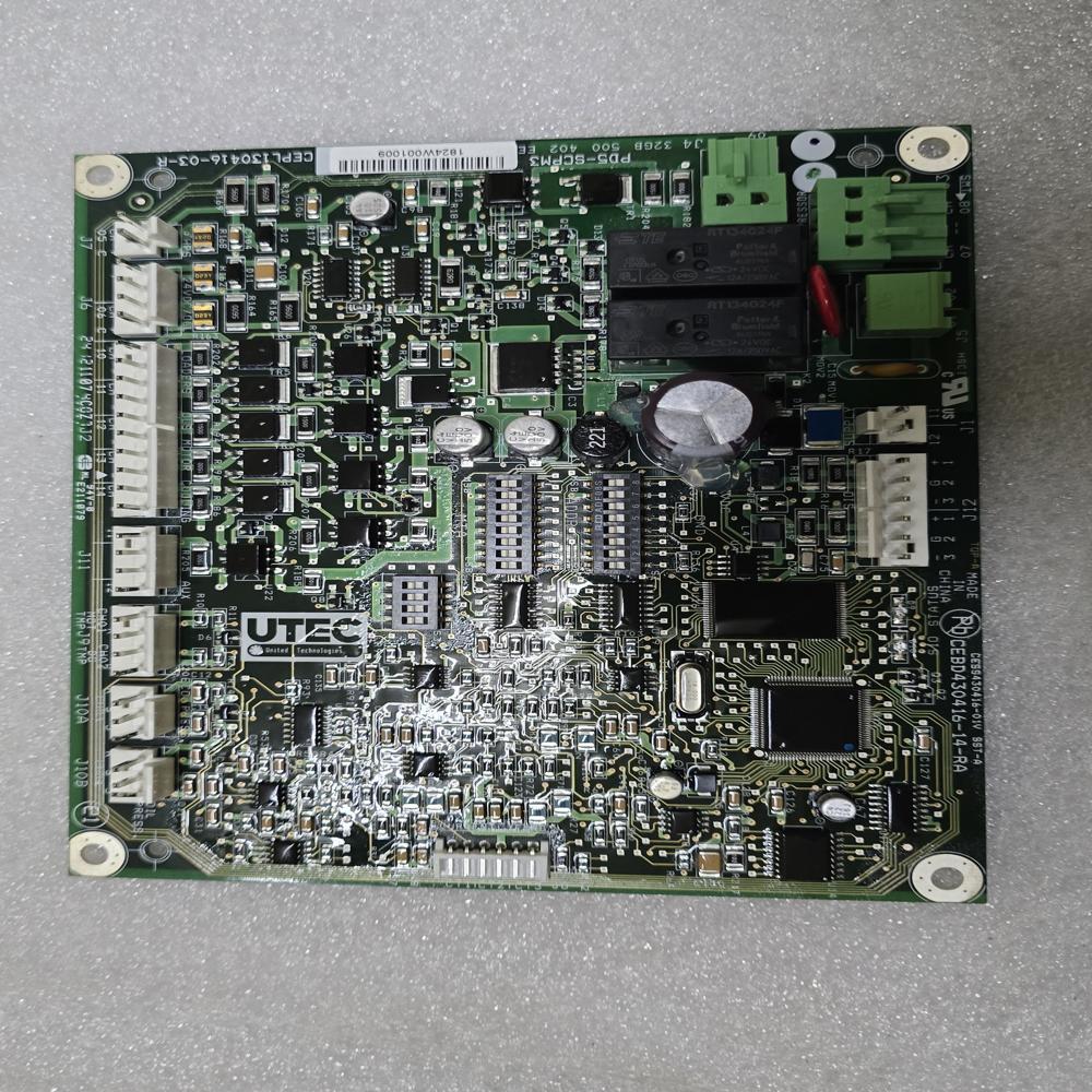
Versatile Connectivity and Robust Power HandlingThis carrier board provides multiple pin headers accommodating digital and analog I/O, sensor, and power connections. Electrolytic capacitors and onboard fuse protection enhance circuit reliability and voltage stability, supporting HVAC system requirements efficiently.
Precision Control and Simple IntegrationThe PCB features a main embedded IC for seamless logic and control functions while offering straightforward firmware programming support. Its mounting holes and compact design (approximately 150mm x 80mm x 20mm) support easy installation in a range of settings.
Thermal Efficiency and Silent OperationWith passive cooling and no active moving components, the board ensures silent operation-ideal for applications needing low noise. Its operating temperature range of -20C to 70C guarantees dependable performance in diverse environments.
FAQ's of Carrier Board:
Q: How can the carrier board be integrated into an HVAC system?
A: The carrier board can be installed within an HVAC control unit using its corner mounting holes. It connects to sensors and interface lines via the provided pin headers, facilitating seamless communication and control of various system components.
Q: What types of input and output connections are available on the board?
A: The board is equipped with multiple digital and analog I/O options, accessible through pin headers. These support connections for sensors, actuators, and external controls essential for HVAC management.
Q: When is firmware programming for the embedded IC required?
A: Firmware programming is needed during initial board setup, application upgrades, or feature updates. The board offers designated points for in-circuit programming of the main control IC.
Q: Where do I connect power, and what voltage does the board use?
A: Power should be supplied to the dedicated power headers, typically at 5V or 12V DC, depending on your application. Ensure the supply is regulated and within specification for optimum performance.
Q: What process ensures protection against electrical faults?
A: The onboard fuse slots accommodate replaceable fuses that safeguard circuits against overcurrent, enhancing reliability and protecting other components from damage.
Q: What are the benefits of passive cooling and multi-layer PCB design?
A: Passive cooling enables silent operation without fans, critical for noise-sensitive environments. The multi-layer PCB improves signal integrity, reduces electromagnetic interference, and supports higher component density.







 Send Inquiry



 Send Inquiry
 Send Inquiry
 Send SMS


 English
 Spanish
 French
 German
 Italian
 Chinese (Simplified)
 Japanese
 Korean
 Arabic
 Portuguese